Reprinted from Technical Papers on the Development of Embedded Electronics
by Vector
Here I would like to highlight some of the most interesting ideas from the set of articles by Vector. This is 6 of 7 posts on this topic.
SilentBSW – Silent AUTOSAR Basic Software for Safety-related ECUs
Coexistence of Safety-related and Non-safety-related Software in one ECU by Protecting Memory Areas
In future vehicles, most ECUs will be “Mixed-ASIL systems” that contain both safety-related functions and functions without safety relevance. This article presents strategies for efficiently implementing these functions based on AUTOSAR.
One solution is SilentBSW – an AUTOSAR basic software that monitors itself and blocks prohibited write accesses to safety-related software.
AUTOSAR and ISO 26262
AUTOSAR addressed the topic of “functional safety” early on. Current versions of the AUTOSAR specification [1] contain a number of concepts that support the development of safety-related ECUs. Examples are the end-to-end protection for exchanging information and the program flow monitoring with a watchdog. In defining these concepts, steps were taken to support ECU developments in accordance with ISO 26262 [2].
Software Development for Safety-related ECUs
AUTOSAR supports the distribution of functions to multiple ECUs. This simplifies functional development, which can be conducted without regard to the mapping of function units on specific ECUs. One consequence, however, is that a disproportionately high number of ECUs are then classified as needing to fulfill safety requirements (Figure 1).

These ECUs would have to be fully developed according to the highest ASIL (Automotive Safety Integrity Level) of their requirements, even if the vast majority of its functions might not be safety-related. Just a single ASIL-D safety requirement would mean that the entire ECU would have to be developed in accordance with ASIL-D.
To avoid this “ASIL lift-up effect” [3], ISO 26262 allows the coexistence of sub-elements with different ASIL levels. This coexistence requires verification that there are no undesirable interactions between sub-elements. Partitioning is a proven method for implementing this “freedom from interference” for software. The following aspects must be considered in this context:
- Memory accesses
- Timing behavior and execution order
- Exchange of information
“Standard Case” of Coexistence
ECUs containing both safety-related and non-safety-related functions are known as Mixed-ASIL systems. For purposes of simplification, in this article any software with a low ASIL is referred to as QM software, and software with a higher ASIL is referred to as ASIL software. A prerequisite for the use of ASIL software is that the hardware design must be adequate for the maximum required ASIL.
The “standard case” category includes systems with moderate ASIL content, where the interaction between the different contents is rather low. In these cases, separating the partitions is implemented very efficiently by separate elements.
Barriers are set up between the partitioned contents; they prevent – or at least detect – propagation of errors with sufficient probability and report them to the ASIL software. This means that only the barriers and safety-related software need to be developed to the relevant ASIL (Figure 2). In MICROSAR Safe – basic software (BSW) developed jointly by Vector Informatik GmbH and TTTech Automotive GmbH – these protective mechanisms are available up to ASIL-D.

Protection against Memory Violations
The Memory Protection Unit (MPU) of the microcontroller is used to limit write access to the memory areas of its own partition. The software that drives the MPU and executes the context switch must support the highest assigned ASIL. This software is part of an AUTOSAR operating system per Scalability Class 3 or 4 and must be developed to ASIL-D. This function is part of MICROSAR Safe and known as SafeContext.
Protection against Violations of Time Behavior and Execution Sequence
Errors in the QM software must not interfere with proper timing behavior of the tasks of the ASIL software. This is achieved by monitoring the defined execution sequence and time intervals between different functions of the ASIL software. AUTOSAR 4.0 defines functions for this purpose.
In conjunction with a safe hardware watchdog, the software detects any violation of requirements and changes the system to a safe state. This does not prevent errors, but their occurrence is detected. This approach has proven to be effective within typically allowable error reaction times. MICROSAR Safe includes this functionality under the name SafeWatchdog.
Protection against Communication Errors
ISO 26262 lists relevant error patterns in the exchange of information, and AUTOSAR has defined algorithms for detecting them by an end-to-end protection. As in program flow, the goal is to reliably detect each occurring error and change the system to a safe state. Monitoring is performed by inserting sequence numbers and a checksum.
To avoid having to assume a safe RTE (Runtime Environment), the E2E Protection Wrapper and E2E-Lib modules perform monitoring above the RTE in a safe partition of the application software. In MICROSAR Safe, these two modules are contained in option SafeCOM.
Coexistence with a Low Portion of Safety-related Software
If the portion of ASIL software is low, it may make sense to have the ASIL software protect itself against undesirable memory changes. The undesirable modification might be detected, or even corrected, by the following measures (Figure 3):
- Redundant and possibly diversified computation – including validation of the ASIL software’s algorithms
- Redundant and possibly diversified storage of data
Deactivation of interrupts in critical areas, e.g. in areas in which comparisons and decisions are made.
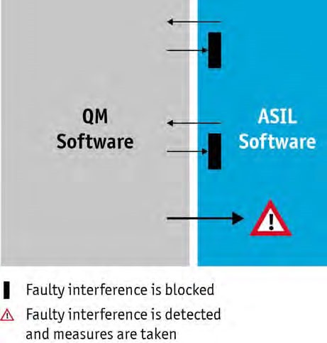
If it is only possible to detect errors but not prevent them, the ASIL software must take appropriate measures to put the system in a safe state. Self-protection against memory changes is implemented in the ASIL software for the specific project. The methods described above are adopted for program flow and communication, because no self-protection is possible in these areas.
Coexistence with Strong Interaction
The method of protecting against memory violations based on an MPU, which is described above, is a very powerful mechanism for implementing any combination of partitions of different ASILs on an ECU. However, the required context switching between the partitions results in runtime overhead that can become critical. This could happen, for example, if a large number of signals are exchanged synchronously between the ASIL application software and the QM basic software, and it is not possible to group the signals.
In such cases, it is advantageous to have the QM basic software run in the same partition as the ASIL application software. But that is only possible if the basic software was developed for the ASIL of the application software. The development effort required for this is often not suitable, because the requirements of the actual functionality of the basic software are typically not classified as safety-related.
This applies to sending out signals, for example, because an end-to-end validation of the communication is still always necessary to detect errors in bus transmission. Therefore, one highly efficient approach is to leave the basic software on the QM level and enable coexistence with the ASIL software without the use of an MPU. MICROSAR Safe offers this type of solution under the name SilentBSW – which is a non-interfering basic software.
To prevent undesired overwriting of memory cells of the ASIL software by the QM software (Figure 4), it is verified for each write command of the QM software that the write access is performed within a valid memory range. One difficulty here lies in a unique property of the basic software: Parts of the program code are generated, and it is not feasible to develop configuration and generation tools per ISO 26262.
The solution is to check the entire code after generation. This is not performed by tests, rather by a specially developed code checker. This validation covers the vast majority of error patterns. The remaining error patterns are covered by code inspections or runtime checks.
Summary and Conclusion
Approaches are already available today for developing ECU software per AUTOSAR and ISO 26262 up to ASIL-D. They include methods for the especially relevant Mixed-ASIL systems, as well as the new SilentBSW approach from Vector, which significantly reduces the execution time requirements for some application cases.
It is not necessary to assume that every requirement of the basic software must be generally classified as safety-related. Rather, it is much more important to implement individual requirements – which are derived from the safety concept for an ECU – in the basic software at the specific ASIL that is needed.
The article is based on a speech of Günther Heling at the VDI conference Baden-Baden-Spezial, VDI report 2172
References:
- AUTOSAR GbR: http://www.autosar.org
- International Organization for Standardization (ISO), ISO 26262-1 bis ISO 26262-9, Road vehicles – Functional safety ISO 26262-1:2011(E) up to ISO 26262-9:2011(E), First Edition 2011-11-15
- Dr. Poledna, S et.al.: Ein ASIL D Plattformsteuergerät für eine elektrische Hinterachse mit Fahrdynamikfunktionalität; VDI-Bericht Nr. 2132, 2011 (English translation of the speech title: An ASIL D platform ECU for an electric rear axle with driving dynamics functionality; VDI report No. 2132, 2011)
Practical Implementation of Mixed-ASIL Systems
A Certified Operating System Simplifies the Development of Safety-related Software
The ISO 26262 standard describes a recognized and standardized process for developing safety-related ECUs in the automotive field. However, only parts of the software in these ECUs are safety-related. The goal is to restrict the additional, intensive development efforts for these safety-related components. It is possible to set up an ISO-conformant mixed-ASIL system, which may contain both ASIL functions and functions without qualification, using an advanced AUTOSAR operating system and two other basic software modules.
The ISO 26262 standard is increasingly being used to develop safety-related ECU software. At the beginning of a standard-conformant development process, the developer performs a hazard analysis and risk assessment of the system under development. The developer establishes safety goals and assigns each of them a specific Automotive Safety Integrity Level (ASIL), ranging from A to D, based on the probability the error will occur, the severity of damage that could result and the ability of the driver to control the vehicle in case of defect.
Assignment of ASILs to all software elements generally results in functional groups with different ASIL classifications. In principle an ECU’s entire software must be developed to the highest ASIL determined for one of these functional groups. This intensifies the development effort to an extreme, because even non-safety related software must be developed to the high requirements of the safety process.
The approach of using mixed-ASIL systems provides a solution. In this case, the functional groups are isolated from one another by suitable protection measures, so that they cannot interfere with one another. This reduces the development effort for the individual functional groups to what is required for their specific ASILs.
The protection mechanisms needed are available in the form of a modern AUTOSAR operating system and two other basic software modules which the ECU manufacturer does not need to develop separately.
Technical Safety Concept
Developers must ensure that the overall system fulfills their safety requirements. None of the system’s software components may put fulfillment of these safety requirements at risk. Therefore, the only safety requirement for software components without safety-related functionality is that they must conform to the principle of freedom from interference ([1] Part 9, section 6.4).
Freedom from interference of software components is defined by three properties:
- Safe memory accesses
- Correct time execution
- Safe data exchange
A component’s freedom from interference can be verified by classic verification measures, e.g. by code reviews. There are also approaches in which a specially developed code checker is used to check the freedom from interference of the basic software [2]. Other measures may be taken in the software to ensure protection against hardware-related disturbances as well.
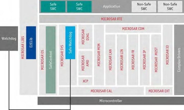
A modern AUTOSAR operating system like MICROSAR OS SafeContext (Figure 1) offers protection against faulty overwriting of memory contents. The protection is achieved by partitioning each functional group into a so-called OS application. Each OS application’s data are allocated in separate memory partitions. Along with the application data, context-related data such as stacks and the contents of important registers are also located in such a memory partition. Access to these memory partitions is prevented by a Memory Protection Unit (MPU), which is part of the microprocessor hardware.
When switching the running task or the Interrupt Service Routine, the operating system executes a context switch. Here, the context data is stored, and the MPU is reconfigured so that it only enables the memory partition for the task or Interrupt Service Routine that is active after the switch (Figure 2). This switch is only executed by the operating system and is safety-related. Therefore, the AUTOSAR operating system MICROSAR OS SafeContext was assigned ASIL D classification and was developed in processes defined for ASIL-D in ISO26262.
Comprehensive Validation Concept
It is important to monitor the program flow in safety-related systems. The Watchdog Manager specified in AUTOSAR (Figure 1) is used for this purpose. This module, which supplements MICROSAR OS SafeContext, is available in the form of the SafeWatchdog [3] developed by TTTech Automotive GmbH, which is qualified to ASIL D. As the name suggests, this component controls the hardware watchdog, and it safely ensures a reset of the ECU in case of error. In addition, this component monitors for correct time flow of the application’s tasks. Developers can set a number of parameters for the monitoring such as program flow, cycle times, minimum/maximum execution times, etc.
The third requirement for freedom from interference, which is implementation of reliable communication, is fulfilled by end-to-end protection (Figure 1). With the help of the E2ELib [4] specified in AUTOSAR, the SafeCOM product protects the data to be transmitted using a CRC and sequential message numbers. Strictly speaking, this does not ensure safe communication, rather just “integrity” in communication. Software cannot protect against data failure due to hardware errors, e.g. a bus line break. To ensure safe communication, additional measures must be taken in the hardware, e.g. in the form of redundant buses.


Integration of Application Software and Operating System
In the ISO standard, safety-related components developed by an external supplier and supplied to the ECU manufacturer are referred to as “Safety Elements out of Context” (SEooC). They include the operating system discussed above as well as the watchdog manager and the E2ELib. During development, the suppliers of such components must make assumptions about the expected safety goals without familiarity with the ECU project. Therefore, as part of integration work ECU developers must check whether the safety goals assumed for the supplied SEooC are sufficient for achieving the safety goals of their projects. Moreover, the ECU developer is responsible for following special integration instructions for the supplied software module. Therefore, each SEooC is supplied together with a safety manual, which contains the integration instructions and assumptions about safety goals.
At first, this may sound like more work. However, upon closer examination, it becomes clear that a similar level of effort must be planned for integrating components that are developed in-house, but the advantage of supplied components is that the effort required for creating these components is eliminated. Overall, this yields significant work savings.
Outlook
The TÜV Nord organization has certified the MICROSAR OS SafeContext operating system developed by Vector for the TMS570 microcontroller, making it the first AUTOSAR operating system to be certified to ASIL D. This implementation is currently being transferred to other platforms. They include multi-core processors which are being used increasingly.
MICROSAR OS SafeContext, used together with the Safe-Watchdog and SafeCOM basic software modules, provides an up-to-date and safe development foundation for safety-related ECUs. In particular, it can be used to cost-effectively implement mixed-ASIL systems.
Besides protecting the application software, the safety process must also protect all of the basic software. Vector offers a variant developed in conformance to ISO 26262 which is distinguished by its ability to achieve the safety goal “freedom from interference in relation to memory access”.
Translation of a German publication in the special edition “Funktionale Sicherheit” of Elektronik automotive, July/2013
References:
- ISO 26262 – Road Vehicles – Functional Safety, 2011
- G. Heling, J. Rein and P. Markl, “Koexistenz von sicherer and nicht-sicherer Software auf einemSteuergerät” (“Coexistence of safety and non-safety software in one ECU”), ATZ special electronics issue of electronica, pp. 62-65, November 2012
- AUTOSAR, “Specification of Watchdog Manager” V2.3.0
- AUTOSAR, “Specification of SW-C End-to-End Communication Protection Library” V3.0.0
Is This What the Future Will Look Like?
Implementing Fault Tolerant System Architectures with AUTOSAR Basic Software Highly automated driving adds new requirements to existing safety concepts. It is no longer sufficient to simply deactivate a function to reach a safe state. In the future, a safe state will require energy and active functionality. This article shows available mechanisms and explains how they can be modularly combined to attain an effective safety concept. It also aims to create an awareness of the challenges of future fault tolerant systems and shows that they can be overcome effectively with AUTOSAR.
In safety-relevant systems of today’s vehicles, the most frequent reaction to a fault is to deactivate or reset the faulty function. This is referred to as fail-silent. It is easy to implement this type of solution, and it is effective for achieving a safe state and maintaining it.
However, E/E systems in the vehicle are increasingly assuming other functions that must remain available in case of a fault, e.g. when a microcontroller fails. This behavior is referred to as fail-operational and in the following as fault tolerant.
In the future, the demand for fault tolerant systems will increase substantially in manufactured automobiles. One example: in some of today’s heavy SUVs, it is necessary to keep steering assist systems active to assure that drivers can handle steering safely. While development for fail-silent systems is now mastered quite well with ISO 26262, issues in the design of fault tolerant systems are still difficult to resolve with ISO 26262. In particular, attempts to come up with a precise definition of a safe state are still causing headaches in this context. The second edition of ISO 26262, whose publication is planned for 2017 or 2018, will not achieve final clarity either. Aside from the requirements set in standards, the following chapters show how existing safety concepts can be extended to fault tolerant systems using AUTOSAR technology.
Modular Safety Concept for Fail-Silent Systems
Safety engineers use a modular concept to efficiently tailor the various safety mechanisms to a specific project (Figure 1). Here they make a rough distinction between measures for microcontroller integrity, measures for functional monitoring and comprehensive measures.
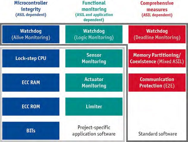
Measures for establishing integrity of microcontrollers are selected according to the highest Automotive Safety Integrity Level (ASIL) of the software that is used. They are independent of the function to be performed, and they are determined by the required diagnostic coverage (DC) for a specific ASIL.
Microcontroller manufacturers often set specific requirements based on their safety analyses. For example, a DC for ASIL D requires built-in self-tests (BITs) that are executed periodically by the software. Generally, starting with ASIL B the probability of occurrence of so called Single Event Upsets (SEUs) must be considered. Microcontrollers in lock-step mode and memory with error detection and correction codes (ECC RAM, ECC ROM) offer effective protection against SEUs. Both safety mechanisms are realized in the hardware, are nearly transparent to software development, and are therefore very efficient solutions.
The developer normally implements additional mechanisms in the application to perform functional monitoring. They include monitoring tasks for sensors and actuators, as well as limiters and program flow monitoring (logic monitoring). Program flow monitoring can be achieved with an AUTOSAR watchdog, for example.
Functional monitoring and microcontroller integrity are defined and implemented according to the specific project. However, there are also mechanisms that are used in nearly every safety-related ECU and are independent of functionality and ASIL. Almost every ECU with ASIL software also executes QM software. To ensure coexistence according to ISO 26262, memory separation and monitoring of time constraints are needed [1]. Memory partitioning is realized by an AUTOSAR operating system with Scalability Class 3 (SC3) that controls a memory protection unit (MPU) with the required ASIL. The watchdog usually handles monitoring of time requirements by deadline monitoring. As soon as safety-related data is exchanged between more than one ECU, communication protection comes into play. AUTOSAR offers an effective safety mechanism for this purpose in the form of end-to-end protection (E2E). Products from Vector that are certified up to ASIL D are available for implementing these comprehensive measures.
Transition to Fault Tolerant Systems
For cost reasons, today’s hardware is designed to be nearly redundancy-free. Therefore, a hardware fault generally leads directly to a serious functional degradation up to complete failure. On the other hand, mature methods exist for quantifying hardware failures, such as those defined in IEC 62380 and SN29500, which permit predictions of the target failure rate [2].
It is often difficult to quantify software faults, since they are exclusively systematic [3]. Timing protection is a suitable safety mechanism for boosting fault tolerance with respect to software faults. Timing protection guards against such faults as infinite loops in software components that prevent execution of the actual functionality. In timing protection, the developer assigns time budgets for the execution times of tasks and interrupt routines and for the blocking times of interrupts and resources. The time intervals between tasks and interrupt routines are also monitored (Figure 2). In case of a fault, the AUTOSAR operating system can terminate the task or interrupt routine that is causing the fault and exclude it from further execution. However, timing protection is only a first step toward the fault tolerant systems that will be needed in the future.

Fault Tolerant System Architectures
Fault tolerant system architectures have been used for many years now in the aerospace industry. For the safety-critical flight control systems, three or four ECUs are redundantly combined to form a complex system. This redundancy in the hardware is of course extremely cost-intensive. Therefore, new approaches must be sought for using fault tolerant systems in the automotive industry. This industry also benefits from lower severity of the consequences of failure in risk assessments.
A feasible system architecture (Figure 3) always consists of at least two channels. In this example, one channel comprises a sensor, a logic unit and an actuator [4]. It is obvious that when the microcontroller of one channel fails, the associated software and its functionality fail as well. Due to their complexity, microcontrollers frequently have the highest failure rates in an ECU. Therefore, proper execution of a function cannot be assured for even a very short time period.

To make this two-channel system fault tolerant, each channel must detect all individual errors for itself and switch itself to passive [5]. Without this requirement, both channels are needed for safe operation of the function. However, in this case the failure rate would double and not be halved as desired. Of course, this system architecture requires a redundant energy supply for the two channels, just as it requires a redundant communications path to relevant partners. The IEC 61508 standard identifies such a system as a 1-out-of-2 with diagnostics (1oo2D).
Software Architecture with AUTOSAR for Fault Tolerant Systems
In principle, introducing redundancies into the hardware also increases complexity in the application. This creates new challenges in the area of control engineering, such as how to achieve controller stability and control actuators when redundant controllers are active at the same time. It is also necessary to reassess data consistency in networks (“Byzantine Generals problem” [6]). From a system architecture perspective, this complexity could be limited by a hot-standby mode, for instance. In this case, only one of the two channels controls the actuators at any given time. If an error occurs on this channel, the other channel immediately assumes control. The AUTOSAR basic software (Figure 4) is useful for simplifying the application development process for the following reasons.
- Re-use: The AUTOSAR components presented above that are used to achieve a modular safety concept can also be re-used by the developer for error detection.
- Use of existing mechanisms: There are two philosophies when it comes to implementing the software of redundant channels: diversity or homogeneity. The diversity philosophy uses different software on the two channels. With the same types of channels and microcontrollers, it is possible to use the same software that is simply parameterized differently for each channel. This is done with the Post-Build Selectable Mechanism of AUTOSAR, which is normally used to develop ECU variants. The use of the same types of channels requires examining errors with the same cause [7].

To enable a quick switchover of control to the other channel in case of a fault, sensor and actuator values as well as status information on the channel are exchanged between the channels (Figure 3). The mechanisms of AUTOSAR make it possible to implement just one configuration of the basic software. The developer can either implement channel switching application-specifically as a software component (SWC) in hot‑standby mode or exploit the flexible configuration options of the AUTOSAR manager components Basic Software Mode Manager (BSWM) and ECU State Manager (ECUM). Today, application-specific software is implemented to exchange the error status between the channels. In the future, however, it is conceivable to specify standardized basic software components for exactly this purpose.
Tool Support
To overcome the added degree of complexity in the future, effective and comprehensive tool support needs to begin in an early development phase. This frees up resources for focusing on application development and relieves engineers of tedious and error-prone work such as manual consistency checking of redundant signals in the system model.
Outlook
Today, on-board AUTOSAR capabilities already permit efficient implementation of safety-related projects. If increased fault tolerance of E/E systems is required, new system architectures will be needed that can handle the failure of the microcontroller as well. This presents new challenges for the application and the basic software.
Nonetheless, the complexity of these types of systems can be mastered using AUTOSAR methodology. Here, AUTOSAR basic software offers an excellent starting point due to its configurability. The associated tool chain simplifies management of the necessary redundancy.
In the future, assistance will be further improved by the basic software and its tools. A first step, however, is to realize that fault tolerant systems also require new approaches in the system architecture.
References:
- Definition of the fault tolerant time interval (FTTI) in ISO 26262-1, 1.45
- ISO 26262-5:9 Evaluation of safety goal violations due to random hardware failures
- ISO 26262-10:4.3 Relationship between faults, errors and failures
- Definition of a system in ISO 26262-1, 1.129
- ISO 26262 Single-point fault metric (SPFM) for ASIL D
- The Byzantine Generals Problem, L. Lamport et al, ACM Transactions on Programming Languages and Systems, 1982
- Definition of a Common Cause Failure in ISO 26262-1, 1.14
