Reprinted from Technical Papers on the Development of Embedded Electronics
by Vector
Here I would like to highlight some of the most interesting ideas from the set of articles by Vector. This is 2 of 7 posts on this topic.
Data Communication in the Automobile
Architecture, Tasks, and Advantages of Serial Bus Systems
What is a “Bus“?
The word “bus” comes from the Latin word “omnibus”, which simply means “for all”.
A common characteristic of all buses is that each connected ECU shares a single input and output and, unlike in networks, information does not have to pass through the ECUs. Thus, when one ECU sends information on a bus, all other ECUs receive the information at almost the same time. The condition “almost” is necessary solely on account of the signal transit time on copper, which is approximately 5 ns/m.
Cross-Vendor Bus Technologies
Intensified competition is ensuring more and more safety and comfort functions in automobiles. As a result, there is not only a continual increase in the number of electronic components in vehicles but also a significantly higher degree of networking and a rapid rise in data volumes since most new automobile functions rely on data exchange. The challenge arising from this is to keep the increasing complexity under control to ensure the continued quality and reliability of functions. For this purpose, the automobile industry has developed standards, such as “AUTOSAR”
(AUTomotive Open System ARchitecture, Figure 6), which provide the necessary transparency on a system or function level. Cross-vendor communication standards such as the serial bus systems CAN [2], LIN [3], FlexRay [4], MOST [5], and Ethernet [6] ensure more transparency on the lower communication levels.
- CAN (Controller Area Network) is used mainly in the drive and chassis areas and in the operation of the vehicle.
- LIN (Local Interconnect Network) is used to control simple comfort functions, such as the air conditioning, seats, mirrors, and windows.
- MOST (Media Oriented System Transport) has long served the infotainment area with transmission of video and audio signals that require large bandwidths
- Also Ethernet is increasingly being used for this. Currently, Ethernet is mainly used for diagnostics including flashing. In the future, however, its main use will be in the driver assistance area, including the park assist and autonomous driving sub-areas.
- Finally, FlexRay should enable the most demanding communication in safety-critical applications such as electronically controlled steering and braking.
However, lawmakers along with the automakers are finding it difficult to push forward here, by trying to avoid the risks in these areas that are highly critical to safety.
CAN was developed in the early 1980s by Robert Bosch GmbH and became an international standard (ISO 11898) in 1994. The founders of Vector played a central role in this development. LIN (ISO 17987), FlexRay (ISO 17458), and MOST came from cross-vendor organizations, namely the LIN Consortium, FlexRay Consortium, and MOST Cooperation.
Vector [7] supports automobile manufacturers and suppliers in networking using CAN, LIN, FlexRay, MOST, and Ethernet with a consistent set of design and development tools as well as with software components and basic software for AUTOSAR ECUs. Advice, consulting services and tools for process management supplement the areas of application.
A comprehensive training program that includes basic seminars for CAN, LIN, FlexRay, and Ethernet rounds out the services. Parts 2 to 5 of this series cover the details of the serial bus systems CAN, LIN, FlexRay, and MOST.
Closing Remarks about the Term “Real-Time”
The term “real-time” is often used loosely or imprecisely, because it is not very easy to grasp. Because I had to use it at the outset, I would like to clarify a few facts about this subject. Whoever wants to know more can draw on other sources. [1]
Part 9 of DIN 44300 (Information Processing), which has been replaced by DIN ISO/IEC 2382, defines real-time as follows: ”Real-time refers to the operation of a computing system on which data processing programs are always operable such that processing results are available within a specified time span. The data may occur randomly or at predefined times, depending on the application.”
For a real-time capable system, it is thus not enough to deliver a measurement or calculation result with the correct value. Rather, this also has to occur within a specified response time. If this is not the case, the system has failed.
According to the theory of real-time systems, the required response time must be calculated for an application running on the system.
People often speak carelessly about “real-time” if a program runs without a noticeable delay. However this definition is not very accurate. It is wrong to use “real-time“ as a synonym for “very fast“, because real-time systems even have to schedule no-load operations in order to also meet real-time requirements under high load.
A distinction is made between hard real-time and soft real-time. The distinguishing criterion is the different consequences of a violation of the real-time requirements.
- Hard real-time requirements: If the system exceeds the required response time, it has failed. Real-time systems must always supply the correct result within the required response time, and the user of a hard real-time system must be able to rely on this. (For example, engine control: if the requirements are violated, the engine sputters and even damage may occur.)
- Soft real-time requirements: Such systems typically meet the required response time but not always. Thus, for example, the required response time reaches only an average or satisfies a different statistical criterion. The time requirements are not absolutely strict, but rather are viewed as guidelines. Exceeding the required response time is not regarded as a failure. It can be exceeded frequently as long as it still falls within a tolerance range. Or, the response time can far exceed the required response time occasionally. (For example, a video conference: When response time requirements are violated, the image “jerks“ but work can continue.)
References
- de.wikipedia.org/wiki/Echtzeit
- de.wikipedia.org/wiki/Controller_Area_Network
- de.wikipedia.org/wiki/Local_Interconnect_Network
- de.wikipedia.org/wiki/FlexRay
- www.mostcooperation.com
- de.wikipedia.org/wiki/BroadR-Reach
- www.vector.com
Reliable Data Exchange with CAN
Priorities Instead of Collisions
The bitwise arbitration has yet another small obvious disadvantage: A bit must have a long enough duration so that delays in sending do not pose problems. An electrical signal has a propagation speed of approximately 200 000 km/s or 0.2 m/ns in copper. Additionally, there are delays through the CAN controller and transceiver. A bit level must last long enough on the bus that the ECUs most distant from the sender can still detect and evaluate it. As a result, there is a reciprocal relationship between the bus length and transmission rate.
Error Detection and the Bull in the China Shop
The probability that errors in CAN messages remain undetected is very low at 4.7 * 10-11 or less [2]. The CAN protocol has defined error detection mechanisms. On the receiver side, these include not only the CRC but also the check of the format (Form Check) and the check according to the bit stuffing rule (Stuff Check). The sender uses bit monitoring to check whether a bit level on the bus corresponds to the send request, and it evaluates the ACK slot.
For example, if statistics indicate that every thousandth message on a CAN bus exhibits an error and the CAN bus operates 1000 hours per year at a data rate of 500 kbit/s, an average bus load of 25% and an average message length of 80 bits, statistically a CAN message with an undetected error would only occur every 4000 years.
The Limits of CAN
CAN is still the most commonly used bus technology in automobiles. However, CAN has systemic limits. Due to the principle of arbitration, CAN itself is not deterministic even during cyclic sending of messages. Using CAN, extremely time-critical applications do not function with sufficient reliability. In addition, only a maximum of one million bits per second can be transmitted with CAN. Another is the high degree of reliability of CAN that makes it too expensive for simple applications that can manage without it.
Driver assistance or autonomous driving as well as comfort applications in the audio area and especially the video area require significantly higher data transmission rates and place higher demands on timely availability of data. Bus systems such as FlexRay and networks such as MOST and Ethernet have been established in these areas. But CAN also has been further developed, and an expansion of CAN, called CAN FD, is now available that enables significantly higher transmission rates. The revised CAN standard ISO 118981:2015 containing CAN FD has been in place since December 2015.
On the other end, LIN (Local Interconnect Network) fills the gap when it comes to cost-effective networking of sensors and actuators in the comfort area, such as for control of power windows, seats, external mirrors, sunroofs, and the air conditioning.
References
- de.wikipedia.org/wiki/Controller_Area_Network
- Unruh, J.; Mathony, H. J.; Kaiser, K.H: Error Detection Analysis of Automotive Communication Protocols. SAE International Congress 1990.
- www.vector.com
- www.vector-academy.com
- Christmann, E.: Data Communication in the Automobile – Part 1: Architecture, Tasks, and Advantages of Serial Bus Systems
- elearning.vector.com
FlexRay for Data Exchange in Safety-critical Applications
FlexRay is going into production for the first time. It will appear on the BMW X5, which was presented to the public at the Paris Auto Salon in August 2006, and it can be purchased in Germany beginning in March of this year. Within its active chassis system, FlexRay provides for secure and reliable data transmission between the central control module and the four satellite ECUs, one located at each shock absorber. This article traces FlexRay’s path into the automobile and explains the key principles of FlexRay bus technology.
Requirements of Future Data Transmission in the Automobile
Implementations of ever more challenging safety and driver-assistance functions go hand in hand with the increasingly more intensive integration of electronic ECUs in the automobile. These implementations require very high data rates to transmit the increasing number of control and status signals. They are signals that not only need to be transmitted extremely quickly; their transmission also needs to be absolutely deterministic.
That is the reason for the growing importance of communication systems that guarantee fast and deterministic data transmission in the automobile. Potential use of by-wire systems further requires the design of fault-tolerant structures and mechanisms. Although by-wire systems may offer wide-ranging capabilities and the benefits of increased design freedom, simplified assembly, personalization of the vehicle, etc., data transmission requirements in the automobile are elevated considerably, because these systems belong to the class of fail-operational systems. They must continue to operate acceptably even when an error occurs. CAN cannot satisfy these requirements due to its event-driven and priority-driven bus access, its limited bandwidth of 500 Kbit/sec based on physical constraints in the automobile, and lack of fault-tolerant structures and mechanisms [3].
FlexRay – The Answer to Heightened Data Transmission Requirements in the Automobile
The certainty that CAN could hardly be expected to satisfy growing data transmission requirements in the automobile over the mid-term, led to the development of a number of deterministic and fault-tolerant serial bus systems with far greater data rates than CAN. Examples include: TTP (Time Triggered Protocol) [4], Byteflight [5] and TTCAN (Time Triggered CAN) [6]. Although a development partnership was created as early as 2001 between Audi and the TTP promoting company TTTech, and although Byteflight was successfully applied to BMW 7-series cars in 2001, it is Flex- Ray that has prevailed in the automotive industry.
An important reason for the success of FlexRay was the founding of the FlexRay Consortium [7], under whose auspices the two motor vehicle manufacturers Daimler and BMW and the two chip producers Motorola and Philips joined forces in the year 2000. Based on Byteflight bus technology originally developed by BMW, the FlexRay Consortium created the cross-OEM, deterministic and fault-tolerant FlexRay communication standard with a data rate of 10 Mbit/sec for extremely safety- and time-critical applications in the automobile. Today the FlexRay Consortium is made up of seven “core partners”: BMW, Bosch, Daimler, Freescale, General Motors, Philips and Volkswagen. Gradually, a number of Premium Associate Members (including Vector Informatik [8]) and Associate Members joined the organization. Making a significant contribution to the success of FlexRay was the detailed documentation of the FlexRay specification. The two most important specifications, the communication protocol and the physical layer, are currently in Version 2.1. These and other FlexRay bus technology specifications can be downloaded from the homepage of the FlexRay Consortium [7].
FlexRay Communication Architecture – Time-triggered, Fault Tolerant and Flexible
Just as in the case of data communication in a CAN cluster, data communication in a FlexRay cluster is also based on a multi-master communication structure. However, the FlexRay nodes are not allowed uncontrolled bus access in response to application-related events, as is the case in CAN. Rather they must conform to a precisely defined communication cycle that allocates a specific time slot to each FlexRay message (Time Division Multiple Access – TDMA) and thereby prescribes the send times of all FlexRay messages (Figure 1).
Time-triggered communication not only ensures deterministic data communication; it also ensures that all nodes of a FlexRay cluster can be developed and tested independent of one another. In addition, removal or addition of FlexRay nodes in an existing cluster must not impact the communication process; this is consistent with the goal of re-use that is often pursued in automotive development. Following the paradigms of time-triggered communication architectures, the underlying logic of FlexRay communication consists of triggering all system activities when specific points are reached in the time cycle. The network-wide synchronism of FlexRay nodes that is necessary here, is assured by a distributed, fault-tolerant clock synchronization mechanism: All FlexRay nodes not only continuously correct for the beginning times (offset correction) of regularly transmitted synchronization messages; they also correct for the duration (slope correction) of the communication cycles (Figure 2). This increases both the bandwidth efficiency and robustness of the synchronization.
FlexRay communication can be based on either an electrical or optical physical layer. Speaking in favor of electrical signal transmission is its simplicity, which brings cost advantages. The comparatively cost-intensive optical signal transmission is characterized by substantially better electromagnetic compatibility (EMC) compared to electrical signal transmission.
FlexRay communication is not bound by a specific topology. A simple, passive bus structure is just as feasible as an active star topology or a combination of the two (Figure 3). The primary advantages of the active star topology lie in possibility of disconnecting faulty communication branches or FlexRay nodes and – in designing larger clusters – the ability to terminate with ideal bus terminations when physical signal transmission is electrical. To minimize failure risk, FlexRay offers redundant layout of the communication channel (Figure 4). This redundant communication channel could, on the other hand, be used to increase the data rate to 20 Mbit/sec. The choice between fault tolerance and additional bandwidth can be made individually for each FlexRay message.
Finally, an independent control mechanism (Bus Guardian) ensures that a FlexRay node only gets access to the bus during its turn in the communication cycle. This prevents bus monopolization by a defective FlexRay node (babbling idiot).
CRC-protected Data Transmission
The signals in a FlexRay cluster are transmitted by the well-defined FlexRay message, wherein there is essentially no difference in the formats of the FlexRay messages transmitted in the static segment and those transmitted in the dynamic segment. They are each composed of a header, payload and trailer (Figure 6). The header comprises the five-bit wide status field, ID, payload length and cycle counter. The header-CRC (11 bits) protects parts of the status field, ID and payload length with a Hamming distance of 6. The ID identifies the FlexRay message and represents a slot in the static or dynamic segment. In the dynamic segment the ID corresponds to the priority of the FlexRay message. The individual bits of the status field specify the FlexRay message more precisely. For example, the “sync frame indicator bit” indicates whether the FlexRay message may be used for clock synchronization. After the header comes the so-called payload. A total of up to 254 useful bytes may be transported by one FlexRay message. The trailer encompasses the header and payload-protecting CRC (24 bit). Given a payload of up to 248 useful bytes, the CRC guarantees a Hamming distance of 6. For a larger payload the Hamming distance is 4 [8].
IP and Ethernet in Motor Vehicles
Challenges for the Development Tool, Illustrated by Today’s Applications Until just a few years ago, the prevailing opinion was that Ethernet would never be used for in-vehicle applications, with the exception of diagnostic access. Soon, however, camera-based driver assistance systems will be the first applications to utilize Ethernet technology as a system network. This presents new challenges to automotive OEMs, suppliers and development tool producers, because the Internet Protocol and Ethernet represent a new network technology for motor vehicles. Nonetheless, many of the issues can already be solved.
After the debut of the CAN bus in the Mercedes S-Class in 1991, the LIN, MOST and FlexRay bus systems also became established in the motor vehicle. Today, CAN continues to be used in automotive network architectures in all domains (from powertrain to body). LIN bus technology is ideal for simple and cost-effective data exchange of noncritical signals in the convenience area. Where bandwidths and real-time requirements run into limitations, CAN is replaced by FlexRay or MOST – in cases where it is economically justifiable. In today’s vehicles, one often finds all of the named bus systems, segmented and networked via gateways.
Motivation for Ethernet
Ethernet has long been an established standard technology in office communications, industrial engineering (ODVA standards, Ethernet/IP and ProfiNet) and in the aerospace industry (AFDX®). In the automotive field, Ethernet had already proven itself in the vehicle for diagnostic access. In recent years, other use areas have increasingly been discussed in automotive research and development departments, because Ethernet’s, scalable bandwidth and flexibility spoke strongly in its favor. Nonetheless, a suitable and economical wiring technology was lacking for the motor vehicle.
Currently, the main drivers for Ethernet usage in the vehicle are camera-based driver assistance systems. In camera applications in the vehicle, LVDS technology (Low Voltage Differential Signaling) has been used until now. The shielded cable that is generally used there does indeed assure electromagnetic compatibility, but it is expensive by industry measures, and it is very impractical to install in the motor vehicle. Most recently, a physical layer is available that offers full-duplex transmission at 100 Mbit/s on a CAN-like, two-wire cable (unshielded twisted pair), and in the opinion of various publications it is suitable for use in the motor vehicle [1], [2], [3].
Requirements of an IP Development Tool
First, known requirements of previous bus systems still apply to the development tool. Initially, what is required is a detailed protocol analysis with stimulation option that extends to script-based testing with automatic generation of test reports. The user also expects that the market-proven multibus capability will of course be extended to include Ethernet and IP, so that dependencies between events on different bus systems can be studied. Currently, for example, there is interest in correlation between LIN and CAN, and in the future interest will be between CAN and IP.
As previously, in protocol analysis the user needs easy symbolic access to all relevant application signals as well as the ability to further process them in any desired way – logically and graphically. However, there will also be new requirements, which on the one hand are imposed by the bus physics and on the other by the wide variety of IP protocols. The article explains – based on the current camera example and four other application areas of IP and Ethernet in the motor vehicle – how these measurement tasks present themselves in product development departments from the perspective of the system manager, and which special requirements result for the development tool.
1. Camera – Ethernet as System Network
A camera-based driver assistance system at BMW will be the first production implementation in the motor vehicle to utilize IP and Ethernet as the system network in the vehicle [1]. OEMs and suppliers will use the new BroadR-Reach physical layer to save on weight and costs compared to currently used LVDS technology [1], [4], [5]. BroadR-Reach will be licensed by other producers [6].

An example of a camera system network is shown in Figure 1 together with potential measurement points. As an alternative, it would also be possible to connect all cameras directly via a switch. As in bus systems used so far in the motor vehicle, the data traffic must be observed, analyzed and compared time-synchronously at various points in the network. Therefore, the measurement hardware must initially support the current bus physics (e.g. BroadR-Reach), but must also be open to future physical layers. Desirable are multi-channel taps via tee-couplers, which disturb the system network as little as possible in monitoring. The tee-coupler should also be capable of injecting errors to validate system functionality. Beyond analysis tasks, stimulation or even simulation of entire sections of the network is also required (remaining bus simulation). This poses certain challenges on the measurement hardware.
In the camera application, there are heightened requirements related to time synchronization and Quality of Service (QoS) [4]. They should be addressed by protocol extensions of the Audio Video Bridging standard (AVB) [7]. Now that manufacturers have appeared to reach agreement on the bit transmission layer (OSI Layer 1), standardization is being sought in higher layers as well for cost and testing reasons.
If only because of the different protocols used in the camera application, there are new requirements for the measurement software, so that any desired signals from the payload of the various, some quite complex, protocols can be presented and manipulated according to the application.
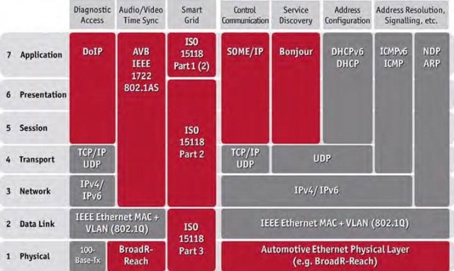
The “Audio/Video” and “Control Communication” columns of Table 1 (based on [7] and Vector) show the protocols used for AVB. There are also protocols for bandwidth reservation and other network management protocols (Table 1, four columns on the right). These and other protocols listed in the table were added based on the application cases considered below.
2. Diagnostic Access
Using “Diagnostics over IP” (DoIP) technology, it is possible to centrally flash all ECUs connected to the various bus systems via high-performance Ethernet access (Figure 2). System development at the OEM must validate this service. Since an ECU is used as the gateway, not only is there great interest in analyzing the transmission of diagnostic data in the various connected bus systems, but on the IP side as well. Relevant protocols are ISO 13400 and IPv4, and possibly IPv6 as represented in Table 1.

3. Electric Refueling Station – Smart Charging
Smart Charging goes far beyond simply plugging into a household electrical outlet. The electric vehicle to be charged is connected to the electrical grid via a charging station. Charging processes do not simply start up; first, the need to charge is communicated. Delaying individual charging processes by fractions of a minute can avoid overloads of the grid. The connected vehicles can also be used as storage media, and electrical provider billing can be automated.
This is made possible by communication between the vehicles and charging station over Ethernet on IP based protocols, in standardization defined in the ISO 15118 standard. The charging station communicates with the grid and the vehicle here. For the systems manager at the automotive OEM, communication between the car and the charging station is quite important. A detailed analysis and validation of the protocols is absolutely essential to safeguard the charging process. The development tool must also support these protocols (Table 1, “Smart Grid” column).
4. Calibration, Debugging, Flashing
For many years now, Ethernet has been used with the XCP measurement and calibration protocol to calibrate, debug and flash ECUs in development. However, Ethernet access is no longer provided in the production vehicle for cost reasons. Therefore, calibration and reprogramming are currently performed using the existing working protocol (e.g. CCP or XCP on CAN). However, if Ethernet makes its way into the vehicle in the near future, measurement and calibration over XCP on Ethernet would also be very attractive in production vehicles due to its significantly higher measurement data rates.
5. WLAN and Car2x
Car2x is understood as the external communication between vehicles and the infrastructure. Applications range from convenience functions to traffic flow optimization and heightened traffic safety (driver assistance systems). The technology is already in pre-production development, and standardization is quite advanced. It is IP-based, and the IEEE 802.11p standard is used as the physical layer.
From the perspective of the systems manager measurement technology interest in Car2x applications extends to beyond the boundary of the individual vehicle to a number of other vehicles and RSUs (Roadside Units) in the near environment.
The ECU to be evaluated not only communicates with bus systems located in the vehicle, but also over the air interface with other traffic participants. The development tool must therefore support these IP-based standards as well. In addition, other requirements arise in the high-frequency range (WLAN in the 5 GHz band).
New Variety of Protocols for Applications and Measurement Tool
Table 1 summarizes, by examples, the various application-dependent transmission layers and protocols, which the development tool must support simply based on cases occurring so far. Some of the protocols used in the area of office communications are found here, while many others may be omitted, and certain others are added. The table shows in light gray those protocols that can be adopted from office communications. Those added due to the new automotive application are shown in red.
The measurement system has the task of resolving all relevant protocols and placing all network events in a causal relationship (correct sequence). Here it is desirable to be able to represent all bus domains with a common time base and with sufficient precision.
Validation of IP Production Projects
As the evaluation of the above application cases demonstrates, causality or even time analysis extending over multiple bus systems make it difficult to impossible to utilize standard Ethernet tools from office communications for multi-bus applications in the vehicle. Ethernet in the office field is not the same as Ethernet in the automotive field. The same applies to the specific Internet protocols that are used. They differ in type and complexity, depending on the application – as significantly as the requirements of the physical layer differ.
A suitable engineering format is important in representing the signal structure of the protocols in the development tool and in generating the embedded code. DBC format is the commonly used engineering format for CAN, while FIBEX is commonly used for FlexRay. However, the DBC format is no longer adequate as a database format for the new Ethernet and IP based system network. From the perspective of tool suppliers, it would be helpful if OEMs could agree on a common engineering format. Suitable candidates would be FIBEX 4.0 and AUTOSAR System Description formats. Experience from other industrial fields indicates that tool producers would provide suitable development tools for analysis and code generation soon thereafter.
Outlook for Vehicle Networks
In-vehicle use of CAN is expected to continue much longer than ten years into the future, while all of the other bus systems discussed here will be used for at least ten years.
Nonetheless, applications will increasingly tend towards the use of IP and Ethernet due to growing requirements with regard to bandwidth, flexibility and cost-effectiveness.
In upcoming years, multiple bus systems networked over gateways will be found just as they now exist. Ethernet and IP will simply be added. As in the case of the camera application, new challenges will arise on all protocol levels in future IP applications, yet it will be possible to overcome them with suitable development tools.
Outlook for IP Development Tools
In the automotive field, development tools conceptualized for IP continue to be advisable. On the one hand, they must support all protocol levels, but on the other they must also fit into the typical industry tool landscape. Suppliers are especially called upon to provide suitable development tools for validation of product development projects at the OEM. Naturally, this includes support and ideally tool producer assistance product introduction as well.
Today, Option Ethernet, which is based on the proven CANoe simulation and test tool from Vector Informatik, already covers the described requirements for an Ethernet development tool. With its wide variety of Ethernet-specific functions and multibus capability, CANoe.Ethernet can help to reduce development time, allowing valuable resources to be used more effectively on the application side (Figure 3). CANoe.Ethernet for automotive network development offers the same development convenience as is already the standard for the established CAN, LIN, MOST and FlexRay bus systems. The development tool exhibits a high degree of scalability and basically offers three inter face options (Figure 4). In the simplest Case 1, it works with any network cards existing on a Windows computer. If BroadR-Reach is used, or if it should also be possible to inject errors, then in the future a device of the new VN56xx product line could be used as a hardware interface (Case 2).
This significantly improves time synchronism between the IP channels and with other bus systems. If real-time behavior is required, CANoe.Ethernet could be operated together with the real-time hardware VN8900 in the future, which of course works seamlessly with the VN56xx interface hardware (Case 3).

Literature:
- Bogenberger, R., BMW AG: IP & Ethernet as potential mainstream automotive technologies. Product Day Hanser Automotive. Fellbach, 2011.
- Neff, A., Matheeus, K, et al.: Ethernet & IP as application vehicle bus in use scenario of camera-based driver assistance systems [German lecture]. VDI Reports 2132, Electronics in the motor vehicle. Baden-Baden, 2011. pp. 491-495.
- Streichert, T., Daimler AG: Short and Longterm Perspective of Ethernet for Vehicle-internal Communications. 1st Ethernet & IP @ Automotive Technology Day, BMW, Munich, 2011.
- Nöbauer, J., Continental AG: Migration from MOST and FlexRay Based Networks to Ethernet by Maintaining QoS. 1st Ethernet & IP @ Automotive Technology Day, BMW, Munich, 2011.
- Powell, S. R., Broadcom Corporation: Ethernet Physical Layer Alternatives for Automotive Applications. 1st Ethernet & IP @ Automotive Technology Day, BMW, Munich, 2011.
- NXP Develops Automotive Ethernet Transceivers for In-Vehicle Networks November 09, 2011, NXP develops automotive ethernet transceivers for in-vehicle networks.
- Völker, L., BMW AG: One for all, Interoperability from AUTOSAR to Genivi. 1st Ethernet & IP @ Automotive Technology Day, BMW, Munich, 2011.
Challenge of Ethernet Use in the Automobile
Flexible Interfaces and Software Tools Simplify ECU Development
Already this year, Ethernet will be used as a system network in the first production vehicles. Therefore, the next step is to integrate Ethernet with established technologies in the automotive industry: CAN, FlexRay, LIN and MOST. Functional development tools exist for them, which make it easy for developers to analyze heterogeneous networks. On the Ethernet side, however, only standard tools from office communications exist, but they do not support the special physical layers and IP protocols of the automotive world. Therefore, development and test tools are urgently needed that can be used to analyze and test existing bus systems together with Ethernet networks. But what would be the exact requirements of these tools?


