This is a lecture 5 of the Systems Engineering curriculum from MIT and edX, Engineering the Space Shuttle.
Links to the lectures:
- Origins of the Space Shuttle or The Making of a new Program
- Development of the Space Shuttle
- Bureaucratic Space War
- Political History of the Space Shuttle
- Space Shuttle Orbiter Subsystems
- Orbiter Structures & Thermal Protection System (TPS)
- Space Shuttle Main Engines
I don’t think most people realize how close the margins were there. The next time we go to the moon, we’re going to find out how hard it really was.
Images are credit to NASA.
Space Shuttle Orbiter Program Manager
Introduction by Jeff Hoffman
I’ve already introduced Aron Cohen and you heard him in lecture two talk about the early history of the space shuttle program from a manager’s perspective. In this lecture professor Cohen introduces the second part of this course dealing with space shuttle subsystems. He gives an overview of these systems which will be followed by much more detailed lectures by the individuals who actually designed and operated the individual systems.
This lecture is actually a compendium of two lectures in the original 2005 course which is why you may notice the professor Cohen is wearing a different jacket and tie in the latter part of the lecture compared to the first part.
This lecture is not overly technical and should be a good introduction for everyone to the many sub-systems that had to be developed for the space shuttle.
In lecture 2 professor Cohen talked about how in a big engineering design project you work through the various stages and the first stage is phase A where you come up with the basic concepts. I think the level of detail of the system and subsystems that he’s given in the last lecture and today, we could look at as being on the phase A level to show the basic feasibility and the overall structure.
Those of you from AeroAstro have certainly been familiar with our approach to systems engineering which we call CDIO: Conceive, Design, Implement, which actually means manufacturing tests, and Operate.
In these first few lectures this could be looked at as phase A where we Conceive, and then the detailed Design is phase B, that ends with the Critical Design Review after which in principle you’re supposed to be ready to cut hardware, and then you get into the phases CD mapped to Implement where you actually build and test, and then, of course, we operate.
My background, the way I got into engineering and I probably should have mentioned this at the beginning as sort of truth in advertising, is I was never trained as an engineer unlike Professor Cohen. I was actually trained as an astrophysicist, but when I went to NASA, I spent so much time working with all the technical systems and interacting with the engineers and the people who used them that I learned how these systems are designed and particularly operated. My approach to a lot of these engineering situations is very much from an operator’s point of view, and I’ll try to emphasize that as we go along. It’s very important, right from the beginning of the design, that you think about how you’re going to operate the system. We have had too many examples that I’ve come across where you build something without really thinking of how the system is going to be maintained and taken care of. One of the things that we have been doing for the last few years is to take a group of undergraduates down to the Kennedy Space Center every January during interim activities period and have them spend a couple of weeks with the engineers and technicians who have to maintain and operate the shuttle system, and they hear lots of stories from these engineers and particularly from the technicians who often would say: ‘Boy, I’d like to have a chance to talk to the person who designed this little system, you know, I have to get my hand all the way around and it takes five hours to turn the bolt.’ Or something more fundamental and we’ll probably discuss this when we talk about the main engines, the fact that originally the main engines were supposed to be reusable without being taken out of the shuttle so that you could cycle them many times. Well, it turns out that one in order to get sufficient confidence that the engines are ready to fly we really do have to take them out after every flight and they’re extensively borescoped and you look inside. But some of the engineers in the main engine shop pointed out that, for instance, if certain diagnostic test equipment had been built into the engine so that you could have taken data as the engines were shutting down over and above the data that we actually get, possibly we would have been able to reduce considerably the maintenance on those engines. So again, the shuttle was the first time we had really tried to design reusability into a space vehicle and engines and we’ve learned an awful lot.
It’s very important when we discuss the systems in the course that we don’t just look at the detail design but we also consider the operations.
So in that spirit, Professor Cohen is going to continue his introduction to the shuttle systems.
Space Shuttle Orbiter Subsystems
- Thermal protection system
- Structures
- Space shuttle main engines
- Hydraulic, auxiliary power, fuel cells. OMS, & RCS systems
- Guidance, navigation, and control
- Environmental control & life support in crew cabin
- Landing & mechanical systems
- Communications
- Electrical power
Above is the list of the hardware subsystems.
You’re going to hear a technical briefing on the thermal protection system and the structures by Tom Moser who actually did the work, he was what I call my subsystem manager on the shuttle in the early days of the program.
You’re going to hear a technical briefing on the space shuttle main engines, a very detailed briefing by J.R. Thompson, Jr., who was a project manager of the main engine at Marshall Space Flight Center, then he became a director of the Marshall Space Flight Center, and then he was a deputy administrator of NASA and a Vice President of Orbital Sciences.
You’re going to have a detailed briefing on the hydraulic system, the auxiliary power system, fuel cells, orbital maneuvering system (OMS), and the reaction control systems (RCS). That’s going to be by Henry Cole.
Guidance, navigation, and control is going to be by Phil Hattis from the Draper Laboratories.
Environmental control and life support in the crew cabin is going to be by a man that’s currently working at the Johnson Space Center, Walt Guy who actually did this job for the Apollo.
Most of these people, by the way, did the same thing for the Apollo that they did for the shuttle. So a very similar job and you can ask these people about the Apollo program as well as about the shuttle.
Landing & mechanical systems by Alan Louviere.
Communications and electrical power we are really not going to brief. Although, we’ll talk electrical power when we talk about fuel cells but we’re not really going to have a discussion on communications.
- Aerodynamics
- Aerothermodynamics
And then we’re going to have some analytical studies on aerodynamics and aerothermodynamics.
Subsystems


Orbiter Structure
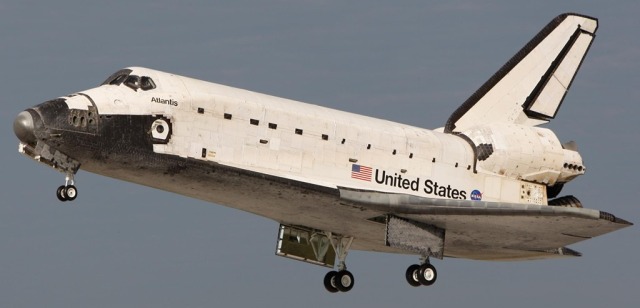
Let’s start off with the orbiter and show you what it looks like and talk about some of the sub-systems.
The Orbiter’s Reaction Control System (RCS) comprises the forward and aft RCS. The forward RCS (FRCS) is located in the forward fuselage nose area. The aft (right and left) RCS is located with the Orbital Maneuvering System (OMS) in the OMS/RCS pods.
The Reaction Control Systems is used primarily in orbit and to get ready to de-orbit. The OMS is used to help you to get into and out of orbit. We also use RCS at high altitudes during entry but eventually the loads become so high that the RCS becomes not effective.


You have main and nose landing gear. Nose gear is shorter than the main landing gear because it saves weight. Also, when you land, by having the nose down, aerodynamic force pushes the orbiter down on the runway, which increases your stability. And since you don’t have to worry about taking off, if they wanted the shuttle to be able to take off horizontally, they would have had to raise the nose.
There are different landing limits for a planned nominal landing: there is emergency limit, and limits for nominal operations. You can take off with 65,000 pounds (~30 tons). That means, if you have a launch abort and you have to return and land with your payload, you will be landing with 65,000 pounds. But you don’t plan to do that, that’s a one-off deal. If you’re planning to do that, it means you can do it over and over again, and then the limit is 35,000 pounds (~16 tons).
They don’t build it like a Navy carrier landing airplane, I’ll tell you that.
The original breaks were under-designed and we kept having break failures, and that’s why we added parachutes. I took parachutes off because of weight but later put them back on.
We’re going to have a detailed discussion on tires, tires are very, very complicated. You think that putting more plies on the tires, it makes them stronger, but not necessarily, because when you cycle them they get hot and more plies tend to hold the heat in and weakens the tire. So the tires are not a very simple thing to design. These tires can be used five times. Breaks are used five times. Main landing tiers can only be used once, front landing tire can be used two times.


The payload bay is interesting. The payload bay doors are made out of graphite epoxy but were originally made out of aluminum. We went for graphite epoxy because of the weight saving, we can save quite a bit of weight using graphite epoxy compared to aluminum. That was probably at that time the largest composite material used in an airplane.

The main engines of course are in the aft end of the orbiter.

The vertical tail stabilizer and Elevons.

And you got a body flap. It was put on originally to deflect some of the heat from the engine but it turned out to be a control service also. The body flaps and the Elevons are used primarily during entry and a little bit during ascent.

Let me go back to Apollo. We had Apollo designed and we found that the lunar module was too heavy and we could not lift off from the lunar surface, and the engines were already built, the tanks were sized and we couldn’t get off the lunar surface, and that’s not very good deal. George Low was the Program Manager at the time. We were spending in those year dollars 24,000 dollars a pound to get weight out of the lunar module and they scraped the shed, they did everything they could to get any weight reductions. That 24,000 dollars was a bonus to Grumman, we were basically offering them a bonus for every pound they could take off the module. We couldn’t resize the engine, it was already there. They were literally in there with emery cloth shaving down the aluminum from the inside. So, weight could be very critical.
I don’t think most people realize how close the margins were there. The Lunar module was only certified for five pressurizations. And then it was beyond its structural limits.
The next time we go to the moon, we’re going to find out how hard it really was.
We went to the moon with one computer in the command module and service module, and two computers in the lunar module. We had the MIT computer and then we had a strap down system built by TRW.
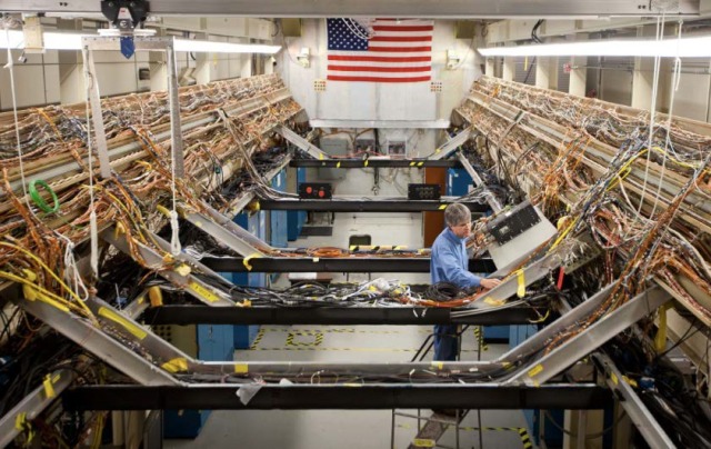
Let me talk about the aft end of the orbiter. We did not have CAD/CAM systems at the time, and let me show you some pictures taken.
That’s the aft end of the orbiter, that’s where the big engines go into.

There’s plumbing, there’s wiring, there’s structure. Had we had computer-aided design at that time, I’m convinced we would have a much neater and better design than we have here.
We had to mock everything up, we mocked it up and we changed it, people bumped their heads on it. You go back in the aft of the orbiter and you wonder how they can do anything, but that was done because we did not have computer-aided design. Airplanes now have virtual mock-ups, you can build virtual mockup right on your computer. We didn’t have any of that.
This picture shows how a crew module looks like from a structural point of view. That was the pressure vessel, and there were the windows. The thing that’s interesting about that, there were very intricate welding techniques.

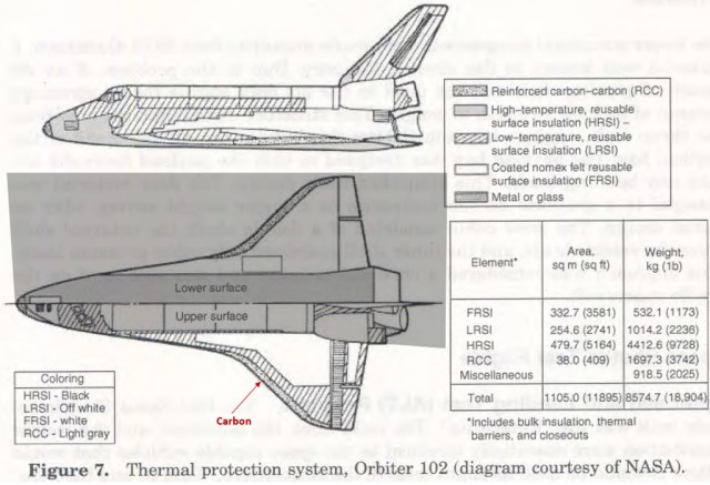
I’d like to now talk about the thermal protection system and the guidance navigation system.

Unfortunately I use English units. Here is an old chart that shows heat rate in BTUs per feet squared, integrated heat load, and radiation equilibrium temperature.
Apollo is number 4. Apollo’s design was about 100 BTUs/Ft2 integrated heat load, heat flux of about 300 BTUs/Ft2·Second, with radiation equilibrium temperature of about 5,000 degrees Fahrenheit. On Apollo we used ablative heat shield. That was a baseline.
Ablative heat shield has a density of about 130 to 140 pounds per cubic foot and it’s not reusable.
Shuttle was about 40,000 BTUs per foot squared integrated heat load, and 50 BTUs per foot squared per second for heat flux, with the Radiation Equilibrium temperature at about 3,000 degrees Fahrenheit.
At that point in time, we had to come down from our baseline knowledge of an ablative material to what we could use and make it reusable and light. There were several competitors at the time: one was a metal insulation René 41, shingle-type material, very thin, very high temperature, and it had very low density; and then of course there was the ceramic material or the so-called tiles, which was basically ceramic material made out of silica, interesting enough, it’s made out of what we call golfer sand that comes from Minnesota, it has very high pure silica content and you make it into a mulch and then you actually bake it, and it comes out in these blocks or tiles, and of course tiles sometimes are hard to bond to the vehicle.
Well, I was orbiter project manager in my hometown in San Antonio, Texas. So, we’d go back to San Antonio to visit my family. My little old aunts would say: their nephew is in charge of the shuttle program and is having trouble making the tiles stay of the vehicle. They could not understand it because they had tiles in their kitchen and the bathroom, they had no trouble at all having tiles stay on. So they could understand why I was having so much problem having the tiles stay on the vehicle.
There was a competition between two research centers: the Langley Research Center wanted to go with the metallic version, and the Ames Research Center wanted to go with the ceramic version. We decided to go with the ceramic version. Tom Moser is going to go in detail about this because he was the guy really in charge of it.


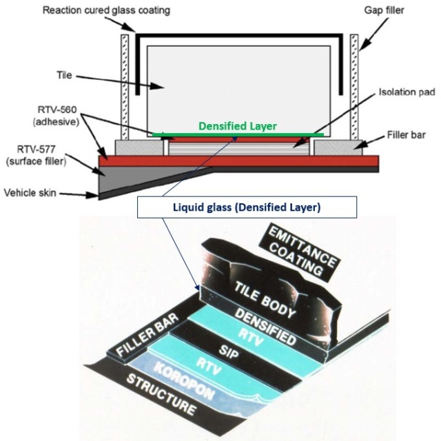
To give you a little background, the problem we had with the tiles is that, because they were ceramic, when you bonded the tiles to the Room Temperature Vulcanizing (RTV) material, which is basically a high-temperature glue, to the Strain Isolation Pad (SIP), you got stress-riser setup and the tile became very weak and broke at bond line of the tile or at the interface. A stress-riser fracture develops when stress in an object is higher than that in the surrounding material.
The tiles could be anywhere from two inches to four inches thick. We had one very clever engineer that saved the day because tiles were falling off and we could not get the vehicle built. He said that if we densify lower quarter of an inch of the tile by putting liquid glass inside that tile making the bottom of the tile a very hard surface, it will no longer break at the bond line, it will break at the tile which had very high loads.
I remember this distinctly, we were doing all these tests and all these analyses and all of a sudden they called me one day and said: ‘Aaron, we’re doing a very simple flatwise tension test and tiles are just coming off the vehicle.’
So, that is what saved the day.
It’s another good example of problems in systems engineering. We worked so hard figuring out how to make these tiles and they are extraordinary. You can take one of these tiles and put one side of it into a kiln, heat it red hot and you could hold the other side of it in your fingers. That’s how good the insulation is. And I guess everybody just sort of figured that we knew how to glue these things in.
We spent so much time working on the efficiency of the tiles to do the thermal protection. This is fantastic tile, it weighs like balsa wood, so it’s anywhere from 10 to 12 pounds per cubic foot, compared to 130 pounds per cubic foot. It can take as high temperature as ablative material and it can be reused. It answered all the question we had about thermal protection. What we did not do though is figure out how we attach it to the vehicle. Everybody just assumed, it’s almost like your relatives, we glue tiles on the bathroom all the time.
We come up with a function structure: What function does it have to perform? Well, it doesn’t actually have to thermally protect the vehicle, it has to stay on. And we forgot about the staying on part, we talked about the thermal protection port. And this thing is so good, its thermal diffusivity is so good that you can get the surface temperature to 2000 Fahrenheit and hold the tile in the palm of your hand. So, it turned out to be a very, very good solution, but we almost blew the day by not coming up with this design.

These have to be individual tiles rather than big long panels because of the differences in the Coefficient of Thermal Expansion (CTE). When a material is heated or cooled, its length change.

That is the point of this Strain Isolation Pad (SIP) and it’s another interface problem, which is part of the Systems Engineering.
The structure of the shuttle is aluminum. Thermally it expands and contracts by several inches, every time you go from night to day. We’ve done these measurements, one side of the orbiter pointed towards the sun, the other side is cold, the orbiter actually bananas by a couple of degrees, and they did thermal test in some of the orbital flight tests where the payload bay clearances could change by a couple of inches depending on the thermal conditions, and designing mechanisms to latch them clothed with those tolerances is not simple.
The orbiter is flexible and expands and contracts as a metal – the tiles don’t, they’re rigid, and if you have too large a tile area, the aluminum is going to bent under it and the tiles will crack. Even with the small tiles, between the aluminum and the tile there’s this strain isolation pad, think of it as sort of like a felt type material, it kind of eases the interface between the two.

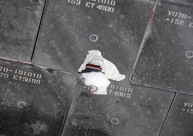
If you look at the tile installation on the vehicle, the tiles are separated by gap fillers which between the missions may need to be fixed. Gap fillers between each one of those tiles are mainly to keep the tiles from vibrating and damaging each other during lift-off.
One of our biggest concerns was how fragile the tiles were. They turned out to be a very good system. We were concerned about losing a tile and then getting heat and having unzippering effect where you lose a bunch of tiles.
These tiles are waterproof. We put scotchgard on them because after a mission the waterproofing boils out.
STS-4 was the hail storm, that was the first time when they recognized the problem.
An engineer from Rockwell International ran a test where he put a densified tile panel in a bucket of scotchgard, rain repellent. He called me about 11 at night and told: “We just ran this test and all the tiles came off.”
I said, “What do you want me to do with that information? We’re getting ready to make a deorbit burn.”
I said, “It was a dumb test, wasn’t it? Is that what happened on the vehicle? Did you actually put the tiles in a bucket of water-repellent material on the vehicle?”
He said, “No.”
I took it upon myself, after talking to Tom Moser, and we didn’t tell anybody. I took a big risk on that, but what could you do about it? There was nothing you could do about it on that test. So that is an interesting case in discretionary project management.
Waterproofing first slipped through the systems engineering. I think it was the fourth shuttle flight, STS-4, the night before launch they had rolled back the payload change-out room, the whole shuttle was exposed. Well, a thunderstorm with hail came through and it pelted the bottom of the shuttle, there were pot-marks all over it, and of course it was raining and people realized that the tiles actually were absorbing material. The outside of the tile is kind of impervious, but once you crack that, the rain can get in. They actually brought a tile expert down from the Cape and they did some calculations how much water it absorbed. It was an early flight so we didn’t have a maximum payload, luckily, because we ended up carrying maybe over a thousand pounds of water into orbit, and there was so much water in the tiles that the orbital dynamicists were able to measure the perturbation of the shuttle’s orbit because of all the water that was evaporated, and of course it was evaporating from the bottom, so that it effectively was asymmetrical and had a propulsive force. It was after that when they came up with the idea of scotchgarding.

If you look closely at each of the tiles, there’s a little hole where they, before every flight, go through with a hypodermics range and inject a little bit of scotchgard. Think how critical it is! You’ve got over 30,000 tiles. If you add one ounce to every tile, you do the math. That’s a lot of extra weight. So you want to put in as little possible scotchgard, but enough to do the job.
Structures
I’m giving you in this lecture what I would call a technical management overview. Mr. Moser is going to go into the details of structures: how the loads were calculated, how the stresses were calculated, how we came up with a basic structure. Structures weigh a lot and we certainly didn’t have all the tools that you have today to make structures more efficient. The materials are also a lot different today.
The forward fuselage, the crew cabin and the aft structure were made by Rockwell International in Downey, the mid-fuselage was made by General Dynamics in San Diego, the wings were made by Grumman, vertical tail was built by Fairchild on Long Island. So we had this vehicle being built all over the country, coming to Palmdale in California for assembly. Some of these places do not exist anymore.
The crew cabin and the forward fuselage are a welded configuration made of aluminum skin stringers.

If you go back down through the mid-fuselage, it is again made of skin stringers.
Vertical tale is machine skins with honeycomb.
The aft fuselage is very complicated, it’s got all the plumbing, all the wiring, all the auxiliary power unit. It is a maze of plumbing and wiring, you can get lost in there and never find you again. It’s made of aluminum while a support structure is boron-aluminum with graphite-epoxy skin panels.

The payload bay doors are made of graphite-epoxy. That was the first time that really a large composite structure was used in a vehicle and that saved a lot of weight. Now it is used quite commonly in the Air Force in a lot of places. One of the problems we had when we built these panels, we found that we got moisture trapped in them, and of course when you heat water coming back it would pop the panels off, so we had to drill little holes in these panels to get the moisture to escape. Those are things you learn when you do new technologies.

Now I’m going to talk about guidance navigation and control. Navigation is determining where you are, guidance is getting to where you want to go, and control is controlling the vehicle and its stability, and its characteristics around the center of gravity.

This chart was originated by the Johnson Space Center and Rockwell International and shows the architecture for the guidance navigation and control system. The contractor for this was IBM federal systems division. We used their computer and they did the software.
Much of the hardware was designed and built by other contractors. Rockwell International did the integration on a system called ‘Shuttle Avionics Integration Laboratory’. It was a vehicle in the laboratory that had all electronics, the cockpit, and everything in it. Hydraulic system simulated the actuators, and the engines were also simulated.
There were actually two laboratories, we had one in Houston and there was one out at Rockwell. You have to appreciate how it was done. It was laid out just like the shuttle. They had the controllers, like they would be in the engine compartment, in the aft end 100 feet away from the crew cabin and the computers, and all the lines, the data and power lines, were laid out as closely as possible to physically duplicate the layout in the shuttle because they were concerned about the timing of signals going back and forth and they really wanted to run the simulation as accurately as possible. And then, of course, you have to have a set of simulation computers to try to determine the environment that the shuttle would be flying in and so that it could make the inputs to the rate gyros and the other parts of the measurement units to try to duplicate the flight regime.
This chart was the original one, it is a little bit different today and I’ll explain the differences that we have.

On the left side there are sensors. That’s the information that you need to do navigation.

That information then is sent to the computer through a multiplexer/demultiplexer or MDM, which is an analog-to-digital converter / a digital-to-analog converter.

Computer does its computations and then sends it to the effectors, whether it’s the Reaction Control System (RCS), Orbital Maneuvering System (OMS), aerosurfaces, booster (SRB) actuators, or main propulsion (MPS) actuators.
To repeat, you have sensors, computation, and actuators.
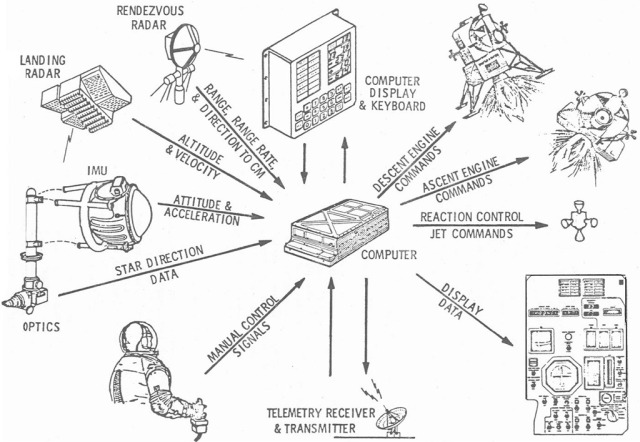
Let me talk about the IMU of the inertial measurement unit. Draper labs is famous for its inertial measurement units.
The inertial measurement unit has gyros to determine angles, and accelerometers. It is a stable platform aligned with a star tracker to get a reference system in inertial space. When you make a maneuver you get acceleration sent to the computer. You integrate it once and get a velocity, you integrate it twice and get position. It is used during powered flight and during entry. The inertial measurement unit is very critical and there are three IMUs on the shuttle and four computers.
When we went to the moon on Apollo we had one IMU and one computer in command and service module, and we had one IMU and one computer in the lunar module, except we did have a backup system in it called the strap down system. Primary system was built by Draper labs at MIT and the back-up system was built by TRW, by two different contractors.
Then you have rate gyros and accelerometer assemblies primarily for assent, for the stability of the vehicle. Air data transducers are for entry. Microwave landing system, tactical navigation, radar altimeter, and rendezvous radar. These are all sensors used in various phases of the mission. Data from them goes through the MDMs or Multiplexer/Demultiplexer to the computers and then to the effectors, which make the vehicle change position and velocity.
There are four computers in the shuttle. That was the real test of the system. We had four computers that were synchronized.
Aerodynamicists decided to make this vehicle statically unstable. That saved a lot of weight. A regular plane is stable, when it gets a disturbance it will come back without any augmentation to its original position. With this vehicle, if you get a disturbance it will diverge, so you had to continually have augmentation, so you had to have a fail operational/fail-safe system, and that’s why there are four computers. It’s fail-operational/fail-safe. You can lose one computer and become fail operational, lose another computer, it means you got two left, and you become fail safe, and you come home.
The real concern about it is, these computers are synchronized, they essentially communicate with each other 440 times a second and they vote on each other, and if one computer is voted out, another computer takes over.
The concern we had was that in doing this we could have a generic failure and lose all computers or we could have a two-on-two split, and these would be sort of diabolical errors which would cause the vehicle to fail. To mitigate, we decided to put in a back-up flight system, fifth computer. It turns out there was an argument there, should we have the fifth computer a different computer made by different people, or should we have the same computer with different people? And we argued long and hard on how to do it, and we had a lot of experience with the Draper Labs (or MIT Instrumentation Labs) who just did an outstanding job the on the Apollo vehicle, both on the command and service module and Lunar module. So we went to the MIT Instrumentation Labs and asked them to take the same computer but put it outside the loop. It’s not part of the redundant set, it’s outside the loop. It gets all the same information that the other computers get but it then can take over if the primary system fails.
We thought to put the back-up flight system in just for a short time to give us confidence in the primary system, but it turns out that we started to put things in it that now we needed it so we could not take it out.
I don’t think we ever really had a diabolical problem in flight. I think we did have one in the shuttle avionics integration lavatory where we had a two-on-two split. We lost one computer once during the approach and landing test where we had the orbiter on top of the Boeing 747 and we separated the orbiter and landed. I remember that first flight, I was sitting in the control station at Edwards Airforce Base, and at that time I smoked the pipe, and when we separated a big X came across the screen because we lost the first computer, power shock from the separation broke the first computer, so we had the second computer. I bit my pipe in two but it did prove that the redundant set did work because it took over and landed. We have had a very successful in-flight test, not planned but it turned out very successful.
Computation produces the information on position which is then sent to the effectors. During the high part of entry information is sent to the Forward Reaction Control System (RCS) or to the Aft RCS, or if you are trying to make a maneuver it is sent to the OMS Actuator. Lower in the atmosphere Aerosurface actuators receive the calculations. During ascent the Thrust Vector Control (TVC), Solid Rocket Boosters (SRB) and Main Propulsion Control (MPS) are engaged.
The flight control system is a very interesting system for entry. Early in the entry because there are no aerodynamics the aerosurfaces are not of any value and the shuttle has to use the Reaction Control System (RCS), but as you get farther into the atmosphere the loads become so high that the Reaction Control System becomes ineffective and then you have to use the aerosurfaces. It is a blended system which has to know when to handle the aerosurfaces versus the Reaction Control System.
There are also displays to the crew which they use to make certain decisions.
That basically is the Guidance, Navigation and Control System (GNC). There is one additional change not shown on this chart, it is the incorporation of the Global Positioning System (GPS) in the Shuttle. It took a long time to do. The GPS gives you position and if you could determine the attitude then theoretically you also could eliminate the inertial measurement unit.
The computers on the shuttle were IBM 4 Pi.
The desire for GPs was to give the shuttle autonomous navigation capability. The shuttle with the star-trackers and the IMUs has the autonomous ability to determine its attitude but it doesn’t know where it is because the inertial measurement units drift over time and so you need to be able to update its state vectors. Originally this was done by just the only way you could do it with radar tracking from the ground, you would track it, you’d get a state vector, you’d uplink the state vector, and then the shuttle would know where it was and then periodically have to update it because of the IMU drift. Once we got the Tracking and Data Relay Satellite system (TDRS) installed you do get navigational information by the Doppler navigation from the signals coming back and forth through TDRS, but it was generally calculated on the ground, so it was not really until the advent of GPS that we got autonomous capability. You need it for things like if you’re going to deploy a satellite for instance, you need to know your position pretty accurately because the satellite is going to take that position and has to do its burn accordingly and obviously for your re-entry burn or for rendezvous it’s critical that you know your position. When you’re doing a rendezvous, the shuttle does have a rendezvous radar. Once you get close enough to the object that you are rendezvousing with such that you can get it either with your radar or they actually use the star-trackers to optically track the object, then you can start getting your relative position with respect to the object even though you may not know your absolute position. And so from that point of view the shuttle gets a certain degree of autonomy.
Maybe I’ll just say one other thing about the computers, because people are amazed at how primitive the shuttle computers are. That’s right, but the original idea and the concepts that we talked about, this was going to be an airplane like vehicle and originally they wanted to use some off-the-shelf hardware. Of course, the AP-101s, as they finally used them, were not off the shelf. These original computers had 128K of memory and the memory they used, I don’t know, if any of you have read back in the history of computing where they actually had the little magnetic ring cores with wires going through, this was really old stuff and they did finally replaced that with a solid state memory with a whapping 256K. And again, probably none of you have dealt with overlay technology, but back when I was a graduate student and we were using computers to do complex astrophysical calculations sometimes you would have a program that was too big for the computer memory and so you’d have the whole program on a tape recorder and you segment it into what you would call overlays and then you would load it one part at a time and it would do its calculations and then you would stop and load the next batch of software. Well, that’s the way we have to run a mission. The computers cannot hold enough software to do assent, orbit and entry. There’s three segments of flight software. You start the mission with the assent software loaded, then when you get up into orbit, you do what they call a major mode transition where you punch a button and everything goes blank and you sort of sit there saying, “I hope this is going to load properly.” And the tape recorder chunks away and then it loads the orbit part, and the same thing when you’re getting ready for entry. Now, the backup system, they decided that they didn’t want to take that risk that if something went major wrong in a major way they wanted the whole flight software on the backup system. And that meant it had to be scrubbed. So the backup system is capable of flying the shuttle and getting it home safely, but there are a lot of capabilities which the main computer system can do which the backup system can’t do just because they’re limited to the amount of software.
The one other thing I’ll say is about putting together this redundant set of four computers, because as Professor Cohen said, the shuttle will not fly without the computers, so it is absolutely flight critical. Hundreds of times a second every computer is looking at the data from all the other computers and they’re all voting and so you have this matrix, just to make sure you understand the way the system works. If computer number one sees a problem with computer number three, it’s likely the computer three is also going to see a problem with computer one because they’re doing something different, but if computer number two sees a problem with computer three and computer three sees a problem with computer two, and computer four sees a problem with computer 3, now you’ve got a three-to-one vote, and so computer three will recognize that it is the problem and it will take itself out of the set. And at the same time all of this information has to go back and forth to the backup computer because if you’re ever going to engage the backup computer it has to be ready to go at a split seconds notice. And the big question is, suppose you get, there are situations where you can get a two-on-two split, and when we run through the simulations to learn how to work this, actually learning the ins and outs of how to work the computer system is probably one of the biggest challenges. Through this training and operating the computers, the astronauts became more knowledgeable than their designers.
– If there’s this danger of a two-on-two vote, was there ever thought to have five computers?
That’s why we put the back-up system in. There’s more to it. It was programmed by different people. Even though it was the same computer, it was programmed and formulated by different people. That was one way of saying: Take away any systematic errors that were in the redundant set.
In other words, they kept the same software requirements document but the actual coding was done by Draper rather than by IBM. That was the other problem, suppose all the four computers are doing the same thing but there was an error in the code which never turned out so that something starts to diverge and what’s your protection against that?
There’s a big argument in doing that. Should you really have a different computer? Should you do everything differently: a different computer, different everything? And of course, there are advantages to that and there are disadvantages to that. So we settled on this.
– You said, this was the first fly-by-wire system. Did it still have a direct link between the pilot and the aerosurfaces?
Fly-by-wire means that when you put an input into the control system, whether you do it manually or whether the computer does it, nevertheless, ultimately your command just goes into the computer, you put the stick to the left saying, “I want to do a left bank.” All you are doing is telling the computer you want to do a left bank, and now a computer has to figure out: “What’s my navigation state? Where am I? If I am coming down through the atmosphere, what’s my altitude, what’s the air pressure, what’s my Mack number?” – and then it’s programmed with aerodynamic control laws. This is one of the big challenges because, as I mentioned the other day, you hit the top of the atmosphere at Mack 25, you do your initial control with the RCS, as the dynamic pressure starts to increase, first the ailerons, the roll becomes active at about 10 pounds per square inch or something like that, you blend the roll control into your aerosurfaces. At about 20, I think it’s pounds per square inch, you can do the pitch control, but because the shuttle is coming in at a 40 degree angle, the vertical stabilizer is pretty much shadowed. So for yaw control you have to keep using the RCS all the way down to about Mack 1, when the shuttle finally pitches down and the vertical stabilizer now has some effectivity.
The problem is that the flight control laws which the computer has to use in order to control the aerosurfaces in the RCS are not constant on your way down. The flight control laws at Mack 15 are very different from at Mack 5. There’s a part of the flight regime, for instance, where if you want to do a left bank you actually have to start by commanding a right yaw and then the cross coupling terms in the aerodynamics causes you to go in the other direction. It gets very complex and the flight control system is continually changing as the entry progresses.
And so the idea that maybe you should have a direct backup link between the pilot’s inputs and the aero control surfaces, although it might give you a warm fuzzy feeling, you could not fly the shuttle directly because to be able to take into account these changing control laws on the way down, you just can’t do it. In fact, unless the shuttle knows where it is, if the navigation state goes bad the shuttle cannot fly. You could have the runway in sight, but if the shuttle’s inertial nav state is wrong you’ll lose control and you can’t land. It’s a very complex system from that point of view.
If you think about the systems engineering that went into this, it takes aerodynamics, it takes flight dynamics, it takes electrical signals, it takes guidance laws, navigation laws, hardware/software, it also has to take into consideration aerodynamic heating, you have to make sure you do not fly outside of regime that you were designed for to fly aerodynamically. This is probably the biggest systems engineering and integration job that you can have, it requires everything.
‒ How big were those IMUs?
It’s a size of a shoebox. On the Apollo, it was a bigger box, the IMU was built for a Polaris Mark II vehicle and was a three-gimbal platform.

Three-gimbal is a big issue because it does not have singularity and you had to maneuver Apollo in a certain way. One of our astronauts, Jim McDivitt, he is quite a famous astronaut and a good friend of mine, said he wanted a fourth gimbal. And there was no way we could get an IMU in that day and time with a fourth gimbal. So what I did, I gave him a fourth gimbal to carry on his flight. At the time, because the IMUs were so big, the fourth gimbal was impossible.
We did not have a gimbal problem on the shuttle.
Most of those sensors are redundant, not all of them, but most of them. The sensor input is put on a data bus and they have multiple data buses, four data buses and each of the computers can read all four data buses, there’s just a tremendous amount of redundancy built in.
They use the star tracker to update the gyros. There’s also a procedure, if you totally lose attitude then you have to go right back and manually take a star site and orient. That we’ve only had to do in the simulator, I never had to do that.
To look at the failure history of this would be very interesting. I know, in my tenure we lost one inertial measurement unit, we lost one computer during approach and landing test. The MDM (Multiplexer/Demultiplexer) was probably the most complicated electronics box of this whole system other than the computer, it’s very, very complicated.
It turns out that at one point in time structures was the most expensive component of a space craft, then of course there was propulsion, and then there became avionics and software. The avionics and software for the shuttle is very, very expensive. It’s probably one of the most expensive things.
Let’s talk briefly about the mission profile.

RTLS: Return to Launch Site
ADA: Abort Once Around
ATO: Abort to Orbit
The guidance system certainly has to take care of launch. There are also four abort modes: Return to Launch Site (RTLS) which you would use if the main engine fails or due to loss of pressurization, Abort Once Around (ADA) is also due to main engine cutoff (MECO), Abort to Orbit (ATO), and Transatlantic Abort (TAL) which is not shown in the diagram.

First stage guidance consists of attitude and throttle schedules as, the function of relative velocity. It’s not completely open loop but it’s almost an open-loop system. It controls the thrust vectors of the engine and the solid rocket booster actuators.
Where systems engineering comes to play, guidance system has to get maximum performance out of the engines, but also it has to shape the angle of attack to control aerodynamic loads because some of the highest loads on the structure are during ascent, control maximum dynamic pressure, and provide flight angle of the SRB stage to allow for recovery of the spent boosters. These are some of the constraints into the systems engineering.

Entry is a task in itself. One of the basic problems is thermal control. The back-face temperature of the tiles on the aluminum structure must be 350 degrees Fahrenheit. The surface temperature may be 15 to 2,000 degrees Fahrenheit, the back face has to be at 350 degrees Fahrenheit because that’s the limit of aluminum. The thermal control for guidance is to keep the vehicle within the temperature constraints of the peak heating region.
After the entry the shuttle goes into the equilibrium glide, constant bank angle is modulated for drag control, then the transition guides the vehicle from the high angle of braking to lower angle of attack, and then you land. All this has to be tied together by the guidance, navigation, and control system.

Hydraulic System consists of three systems and is a 3,000 pounds per inch system and used during ascent and entry to control thrust vector of the engines, for the body flap, elevons, rudder speed brake, actuators of the main engine, doors for the external tank separation, main landing gear, nose wheel steering, and braking. If you lose a hydraulic system, you had a bad day.
It is one place where there’s a single point failure. It’s hard to eliminate all single point failures.

The schematic above shows how the three systems tie in. We’ve never had a loss in the hydraulic system. We tested hydraulic system in the Flight Control Hydraulics Laboratory at Downey, where we had all the hydraulic systems tied together with the computer system and actually flew the vehicle. We call this test of the hydraulic system an ‘iron bird’. We had a failure there at one time early in the program where the system was ruptured causing the loss of the hydraulic fluid. We had to go back and make a major change to the hydraulic actuator system.

To compare shuttle hydraulic system with that on the airplanes, many airplanes have 3 hydraulic systems while shuttle started with 4, but it was so heavy and complicated which made us go to 3. The big difference is how it is powered, on the shuttle power comes from the auxiliary unit which pressurizes the system while on the airplanes it is powered by the engine turbines.

There are 3 APU units on the shuttle. APU generates about 135 horse power, it has a 10-inch turbine which rotates at 10 to 20 thousand RPM, it is fueled by hydrazine. It pressurizes the system to 3,000 PSI.
We tried to copy aircraft design using the same type hydraulic fluid and everything else except we are pressurized by the Auxiliary Power Unit.
I hope what I’m trying to get across to you is how these systems all fit together. You can’t do the guidance navigation control without the hydraulic system, you have the aerodynamics and you have the aerothermodynamics, you got the structures, you got everything that has to fit together and you can imagine the systems engineering problem associated with trying to put all of this together.
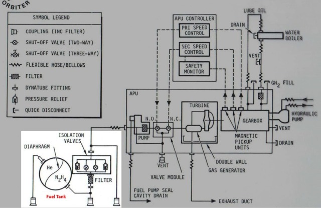
Just to remind you a few other things that you have to deal with when you’re working with a space system that also makes it a little bit different from designing for the ground. For instance, you have a fuel tank with the hydrazine. This is a generic problem with any liquid tanks, once you’re in weightlessness, how do you get the liquid to flow out?
This is a fairly traditional old-fashion design where they have a diaphragm in the tank and on one side of the diaphragm you pressurize it with either helium or nitrogen and that pushes the material. It’s basically sort of like squeezing it out of the bag. Problem is that hydrazine is nasty stuff and in the orbital maneuvering and reaction control systems they decided that for re-usability they didn’t want to use diaphragms. You will probably learn more about some of the details, but there’s a very elaborate screen mechanism which uses surface tension to collect the material. Just getting liquids out of a tank into where you want to go is something you have to worry about in space.

The second problem is a thermal problem. You’re not flying through the atmosphere, so you don’t have air cooling. As you see in the diagram, you’ve got the gear box which is generating a lot of heat, and in order to cool they use water spray boilers. We also do this to get rid of heat from the orbiter before we open the payload bay doors which have radiators. While those are closed it has to be done with a water spray boiler, and so you get rid of all your heat by putting it into a heat exchanger and you basically shoot liquid water and of course in a vacuum the water flash evaporates and that takes the heat way.
Although in essence the control system is similar to airplanes, but even there there’s a lot of special design features that have to be put in because this is a system that has to work in space as well.
Because the system is so complex and heavy, and it needs a lot of maintenance and uses hydrazine which is very nasty stuff, on various occasions there have been studies of could this system be replaced by an electromechanical system as motors become more powerful and battery and fuel cell systems become more efficient?
I think just about two years ago we gave up on the last effort. I think it always turned out that to get an electromechanical system which had enough muscle to move these air surfaces around, it just is beyond what we can do.
